 EN
 Note: Screen data shown is for illustration only
01Operational Overview
View ongoing inspection missions and drone status at a glance.

Threats to your assets begin where you cannot see them.
Critical damage to wind turbine blades and large high-rise structures (bond-line debonding, delamination, internal cracks and more) starts inside the structure. Surface optical imaging alone cannot detect it early, and seeing inside has meant workers hanging from ropes or large cranes being brought in.
Because of these heavy risk costs and the downtime involved, most sites have inspected only to a limited extent, “when the budget allows” rather than “when truly necessary.” Our platform overcomes these limits through technology, enabling continuous, precise Structural Health Monitoring.
Conventional methods compared with the smart autonomous NDT platform.

| Category | Conventional Method (Rope Access / Platforms) | Smart Autonomous NDT System | Business Impact |
|---|---|---|---|
| Worker Position | On the high-rise structure (high-risk exposure) | Ground-controlled | Reduced Risk of Serious Accidents |
| Personnel Required | Specialist rope team + equipment support staff | 1 operator, 1 inspector | Lower labor and operating costs |
| Preparation | Crane rental, access road preparation, rope installation | Minimal take-off space and pre-flight checks | Minimal inspection lead time |
| Changing Targets | Must descend to the ground and climb again | Click the target on the control screen (one touch) | Consecutive inspection of multiple targets for maximum efficiency |
| Resuming Work | Restart from the beginning after any interruption | Resume immediately from the saved stop coordinates | Greater resilience to variables such as bad weather |
| Data Repeatability | Relies on the worker’s judgment (same position cannot be tracked) | Precise revisits based on 3D mapping coordinates | Time-series condition tracking at 6-month and 1-year intervals, enabling predictive maintenance |
Instead of relying on pre-loaded drawings (CAD), the system interprets the structure’s 3D spatial information on site in real time to carry out the mission.
Real-Time 3D Spatial Scanning Digital Twin
After take-off, a Lidar sensor measures the actual shape of the structure (rotor, blade planes, etc.) and maps it in 3D. No drawing data is required.
Intelligent Targeting & Approach Targeting
When the operator designates a target, the system automatically calculates its surface normal (Normal vector) and approaches the inspection zone at the optimal safe approach speed (0.5m/s).
Ultra-Precise Formation Hovering Dual-Flight Alignment
The two drones hold a face-to-face position on either side of the structure (Source–Detector) while following its surface.
Imaging Geometry Alignment Monitoring Geometry Index
The geometric alignment between the two aircraft for X-ray transmission is visualized in real time as an index from 0 to 1. Inspectors can see small deviations caused by wind and capture images at the optimal moment.
Coordinate Logging & Return Coordinated Return
Every inspection position is recorded as a 3D coordinate before the drones return automatically, so the same position can be re-inspected later.
Multi-layer safety protocols protect high-value equipment and the safety of industrial sites.
Hardware Geofencing Minimum Standoff Distance
The system enforces a hard limit that prevents entry within a 3 m radius of the structure under any circumstances.
Real-Time Dynamic Anomaly Detection Dynamic Anomaly
If the blade rotates or vibrates even slightly, the drones immediately retreat to a safe distance and await the operator’s decision.
3-Stage Collision Avoidance Algorithm Collision Avoidance
Even if communication is lost, onboard sensors alone detect surrounding obstacles, and the drones return autonomously after a three-stage avoidance maneuver.
Power, Take-off & Landing Management Power & Sequencing
A warning is issued at 30% battery and an immediate return command is triggered at 20% (with a 2-minute flight reserve). To prevent collisions between aircraft, take-off, landing and target approach are sequenced.
Equipment Neutrality Hardware Agnostic
Not tied to any specific NDT equipment. X-ray and other diagnostic equipment you already operate can be mounted on the drones and used as is.
Independent Closed-Network Operation Air-Gapped
Runs solely on a standalone on-site control system with no internet connection or external cloud, improving security and stability.
Reproducible Records Time-series Tracking
Intuitive records such as “Blade 3, 12 m from the tip” are linked to precise coordinates. Months later, the drones can fly back to exactly the same position to track how a defect has progressed.
Digital Twin Simulation Pre-Rehearsal
Before the real aircraft take off, the entire mission is rehearsed in a simulator that replicates the control software environment, eliminating field variables in advance.
Air — Autonomous Flight Unit
Drone formation (minimum of 2, expandable to 4 or more)
Onboard modules: high-performance onboard AI computer, 3-channel Lidar, dual IMU, RTK satellite navigation system, next-generation flight controller (FC)
Ground — Control Unit
Formation flight control computer, inspection and data control computer
Mission, asset and operator UI
These figures are design reference values and can be optimized for your site conditions and the specifications of the NDT equipment mounted.
Flight and inspection run within a single software package. Mission planning, formation availability checks, control and safety assessment, sensor calibration and diagnostics, and report review all take place within the same interface.
 01
Operational Overview
 02
Operations Cockpit
 03
Mission History
 04
Formation Availability
 05
Formation Monitoring
 06
Domain Reports
 07
Sensor Monitoring
 08
Sensor Calibration
Note: Screen data shown is for illustration only
View ongoing inspection missions and drone status at a glance.
 Note: Screen data shown is for illustration only
 Note: Screen data shown is for illustration only
Look up completed missions by status and wind turbine.
 Note: Screen data shown is for illustration only
Check the availability of both drones required for an inspection mission.
 Note: Screen data shown is for illustration only
Diagnose registered drones through in-depth comparison of real-time telemetry, and check formation status at a glance.
 Note: Screen data shown is for illustration only
Select a domain to view its reports. (Read-only)
 Note: Screen data shown is for illustration only
 Note: Screen data shown is for illustration only
We go beyond the limits of high-rise structure safety assessment.
Tell us the equipment type and scale of the site you want assessed, and we will provide a tailored operating scenario and deployment consulting optimized for your business environment.
Contact Us

Conventional wind turbine inspection presupposes stopping the turbine, and the generation revenue lost while it is stopped far exceeds the cost of the inspection itself.
D-AIR OIS, by contrast, uses advanced technology that follows the rotor’s path while it keeps turning to capture inspection data. You no longer need to accept downtime, and can reduce revenue loss through uninterrupted operation.
The most dangerous failure in inspection is not a “misjudgment” but an “omission.” If any area has not been examined at all, you cannot be sure it is free of defects. D-AIR OIS does not rely on the senses or memory of workers. The system manages a grid ledger that divides the entire blade surface into small cells, finds any cells that were missed and automatically orders them to be re-shot. No report is issued until every cell is filled, which serves as evidence of an inspection with no omissions.
Most existing inspection systems operate on the basis of blade design drawings. As a result, power producers that do not hold the drawings themselves have faced the procedural hurdle of seeking the manufacturer’s cooperation from the very first stage of deployment.
D-AIR OIS, by contrast, is an innovative solution in which ground-based equipment scans the rotating blades directly and determines their geometry on its own. Inspection can therefore begin on site immediately, without prior design data or third-party cooperation.
Operating blades inevitably bend under wind pressure. If the blade is assumed to be a rigid body with no bending, as in conventional inspection methods, the error relative to the actual defect position grows toward the blade tip.
To overcome this limitation, the system accurately analyzes and accounts for the blade’s real-time bending. As a result, it pinpoints damage precisely even at the blade tip, where defects occur most often.
The system does not simply list the defects it finds; it classifies and reports them systematically by risk level. This priority-based listing prevents “critical defects” that require immediate action from being overlooked among numerous ordinary defects, and enables efficient maintenance work.
When adopting zero-downtime inspection, customers are most concerned about the risk of collision when flying near a rotating body, and about data confusion, with the location information of countless images getting mixed up.
The system controls the drone’s flight path geometrically, blocking entry into the blades’ rotation radius and lowering the risk of accidents. Every image collected is also given an accurate location tag through a rigorous verification process. The system proactively rejects any data that is even slightly ambiguous or suspected of error, and keeps only information whose integrity has been proven, giving you a reliable final inspection report.
It does not end with image capture. Everything from registering inspection targets to flight control, coverage checks, defect review and report delivery happens in one place.
 01
Inspection Status at a Glance
 02
Turbine & Blade Register
 03
Pre-Inspection Tracking Accuracy Check
 04
Flight Control & Fault Response
 05
Imaging Coverage Check
 06
Defect Review
 07
Defect Confirmation & Report Delivery
 08
Open Item Management
 09
Inspection History Audit Trail
 Note: Screen data shown is for illustration only
The first screen shows registered turbines, the cumulative number of inspection rounds, work not yet started and defects still awaiting verification.
 Note: Screen data shown is for illustration only
Once turbines and blade geometry are registered for each wind farm, subsequent inspection rounds build up against the same baseline.
 Note: Screen data shown is for illustration only
The alignment of the ground tracking equipment is checked first. If the error exceeds the threshold, the inspection does not start.
 Note: Screen data shown is for illustration only
Operators watch the drone video and rotation tracking status and mark sections to re-shoot on the spot. If communication is lost, captured images are preserved while safety preconditions are rechecked before recovery.
 Note: Screen data shown is for illustration only
Each blade is divided into the leading edge, trailing edge, pressure side and suction side, and imaging coverage is checked for each radial section. For an interrupted session, the remaining sections are clearly shown.
 Note: Screen data shown is for illustration only
Defects found on each blade are reviewed together with their locations, and false detections are rejected while being kept on record.
 Note: Screen data shown is for illustration only
Only verified defects go into the report, which is delivered together with the blade reconstruction outputs.
 Note: Screen data shown is for illustration only
Items that need re-inspection or still await verification are gathered in a single list.
 Note: Screen data shown is for illustration only
Every status change from image capture to delivery is recorded with its time and reason, and cannot be deleted.
The need to visit in person for peace of mind · blind spots you cannot see · unnecessary staffing —
D-AIR addresses all of these on-site problems.
We inspect hazardous places on your behalf, record the site around the clock and report only the results.
You can reduce unnecessary call-outs and risk exposure, and raise your standard of management.
Wherever you are, your site remains under control.
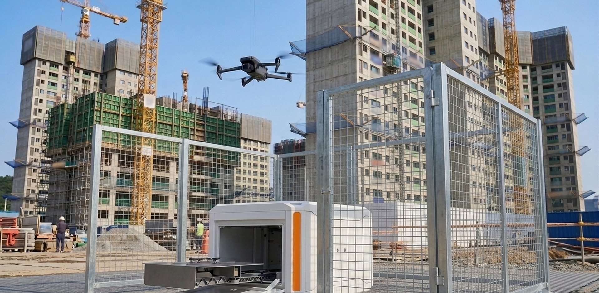
Construction Site Safety & Asset Monitoring
Is it difficult to check a large site in person? Safety with fewer blind spots, accurate progress tracking and careful asset monitoring can all be managed from your office.
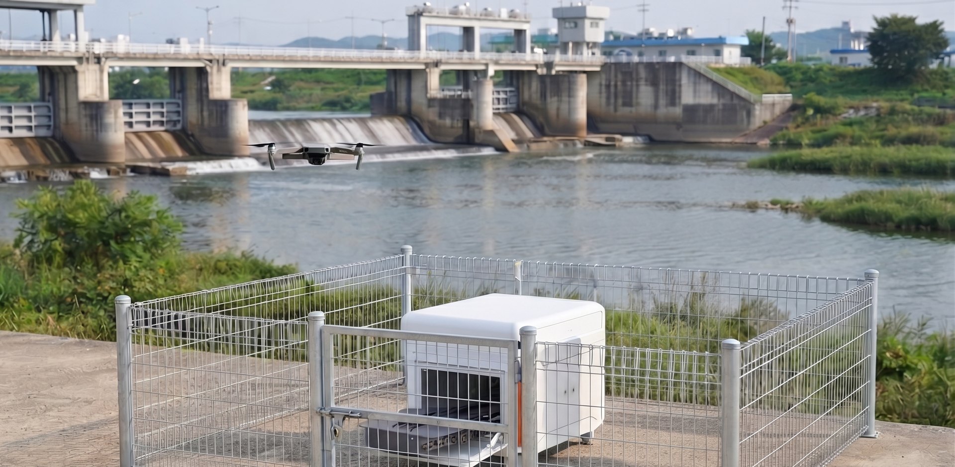
River Facility & Environmental Monitoring
In place of hazardous river patrols, we monitor and report on extensive facilities and environmental changes. You can reduce the time and staffing burden and ease concerns about the site from your office.
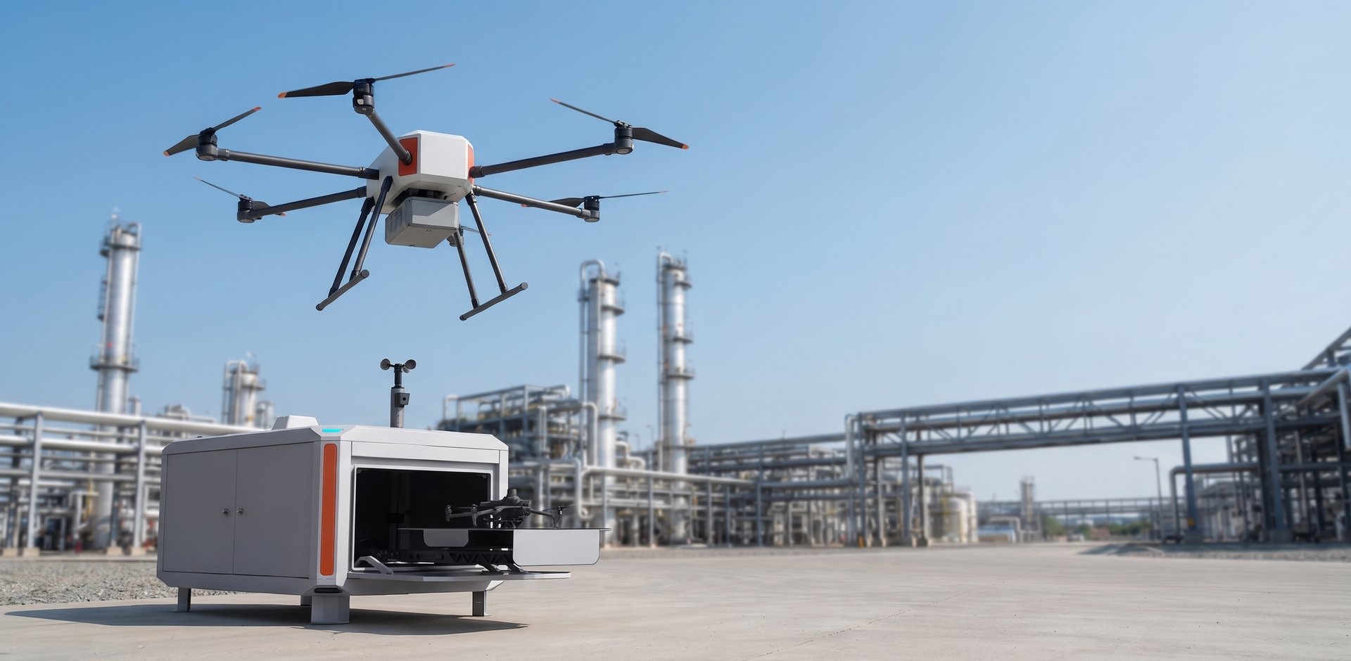
Industrial Facility Safety & Asset Monitoring
Without blind spots across large sites, hazardous facility inspections or unnecessary use of staff, you can reduce the risk of serious accidents and check the condition of extensive site assets from your office.
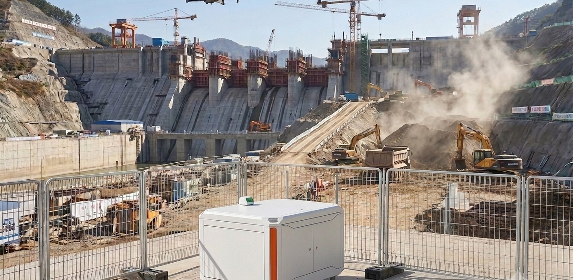
Civil Engineering Site Safety, Asset & Construction Monitoring
Blind spots across endless civil engineering sites, frequent patrols and worry about accidents. You can reduce the burden of travelling to and from the site, and manage everything from construction to assets at a glance from your office.
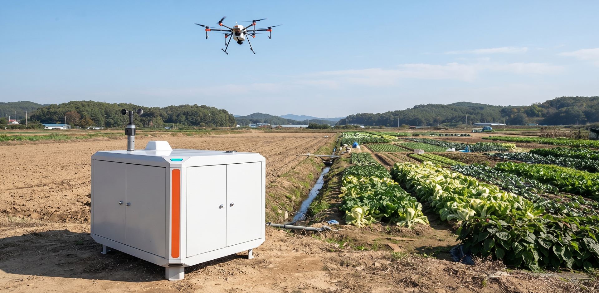
Forest & Crop Ecological Monitoring
Endless forests and fields are hard to inspect on foot, and there is a risk of missing the spread of pests and diseases or the right time for pest control. We support regular tracking of wide-ranging ecological changes, so that warning signs can be detected and addressed in good time.
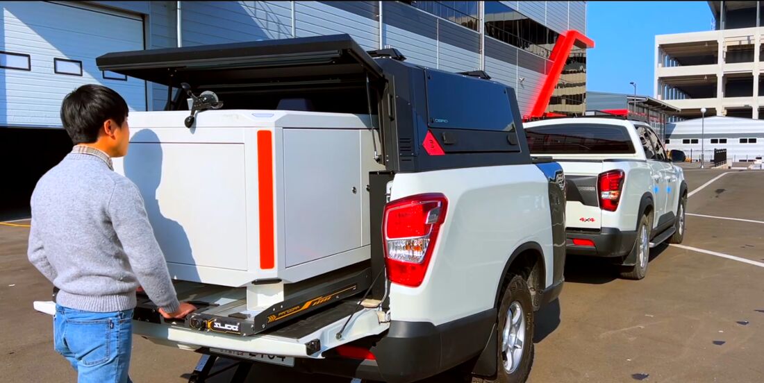
Dock mounted on a mobile trailer for rapid demonstrations
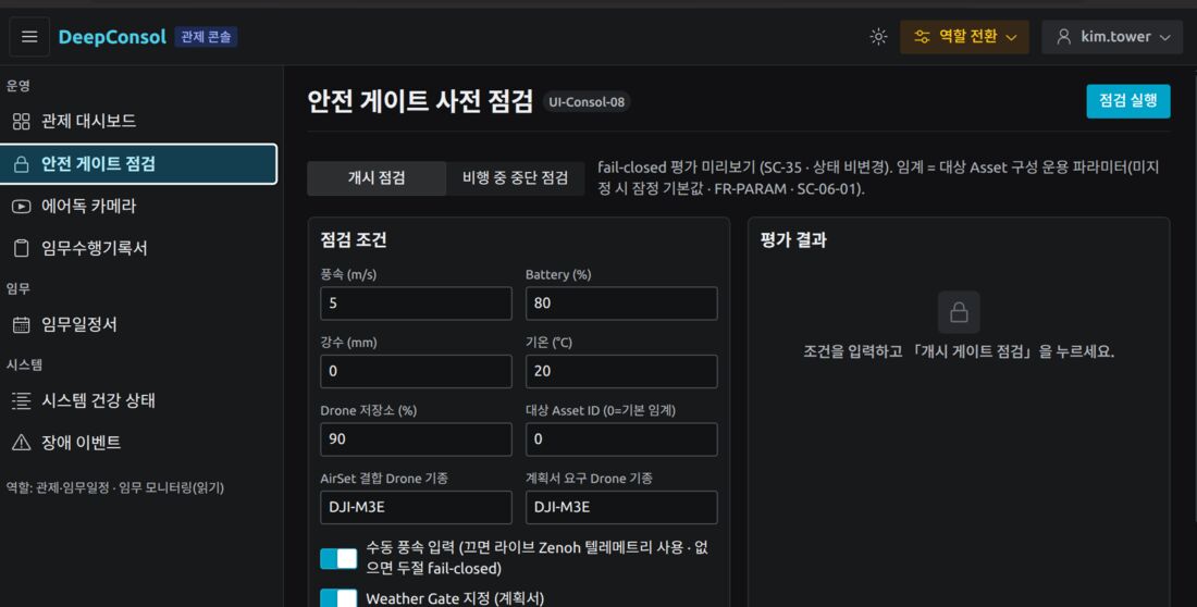
Pre-checks for installation setup and safety
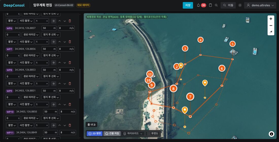
Edit mission plans on the map
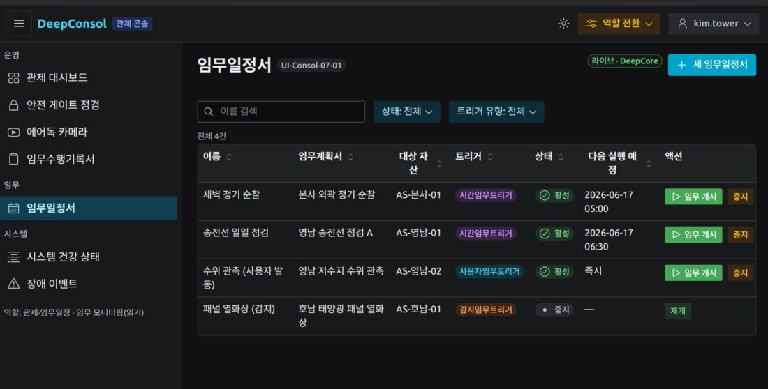
Recurring, scheduled, remote and sensor-triggered launches
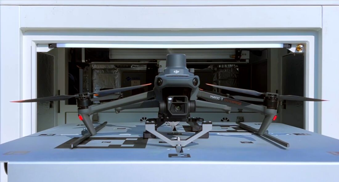
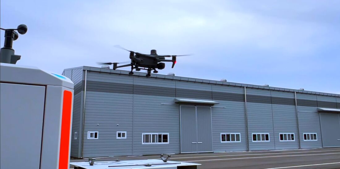
Carries out planned missions according to the mission schedule
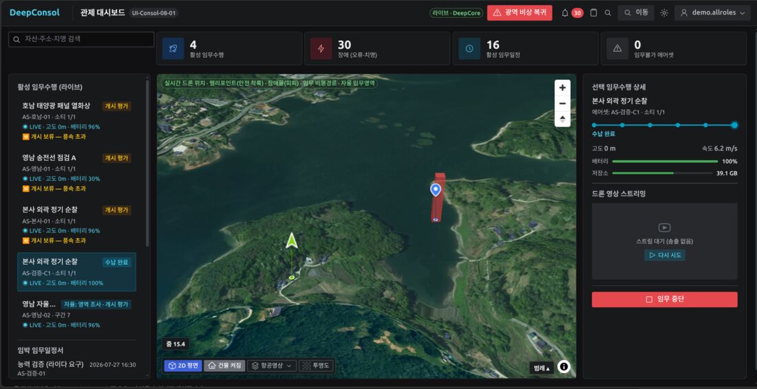
Monitoring of each drone’s position, video and status
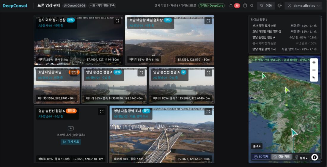
Drone video monitoring for the control room
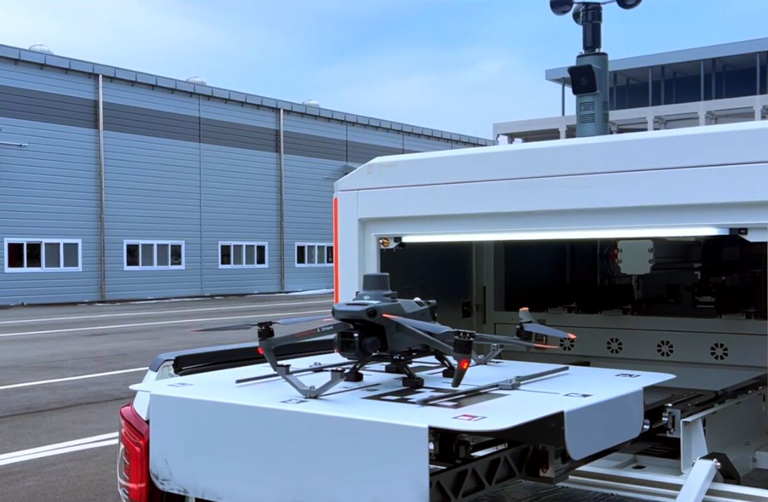
The drone returns to the platform and is stowed automatically
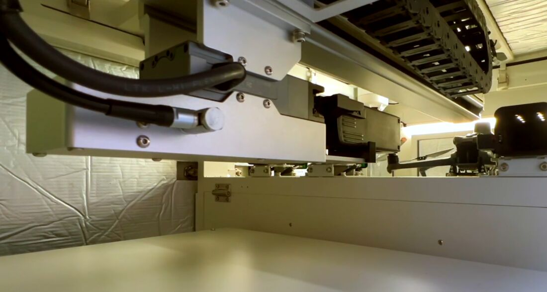
Battery swap in under 3 minutes by robotic arm
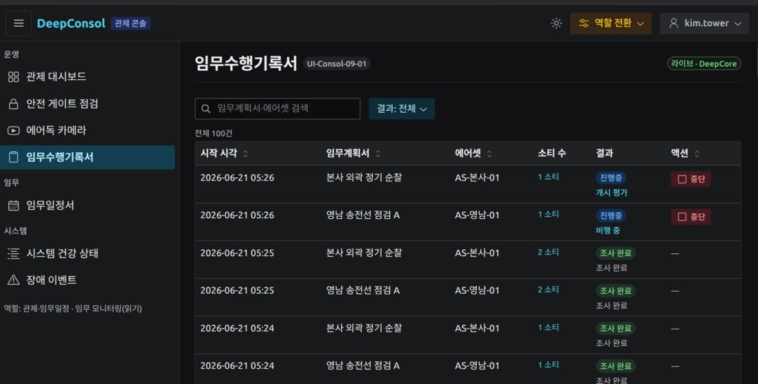
Recording and reporting of mission results
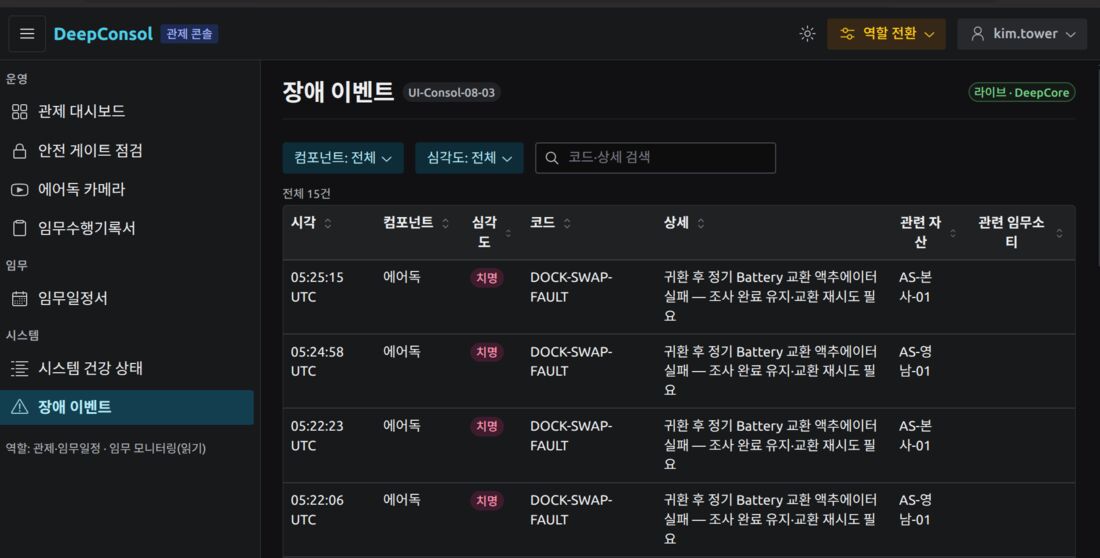
Logging of fault events for fault recovery
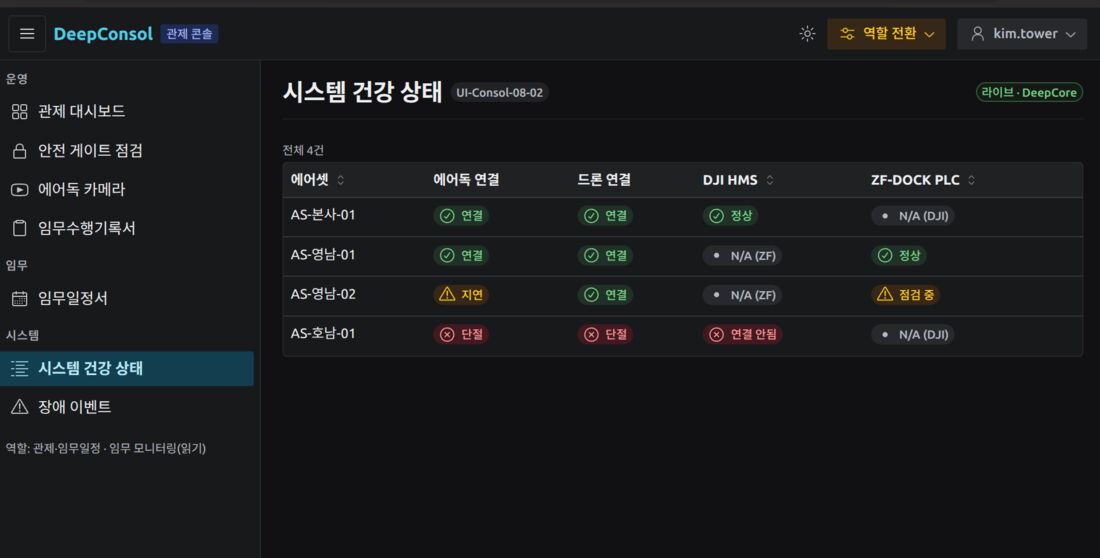
Monitoring of drone and dock health


D-AIR Co., Ltd. | CEO Jeong Yeong-seok | Business Registration No. 415-87-02399
Rooms 220–221, Dowon Sangga Bldg., 216 Munhwa-ro, Naju-si, Jeollanam-do, Republic of Korea
Phone 061w8j6-33pr1-3mt643c02 | Email da5c9hirbaux64028h@crpnab3dever5j.coioem
COPYRIGHT © D-AIR. ALL RIGHTS RESERVED.


